555 Timer Circuit Diagrams
555 timer circuit ic diagram astable mode tutorial random introducing Circuit delay timer counter Ic 555 delay timer circuit
Introducing 555 Timer IC - Tutorial | Random Nerd Tutorials
555 timer circuit diagrams 555 circuit timer diagram does ne555 pinout work mode frequency eleccircuit oscillator draw using building when running astable use block 555 astable timer multivibrator oscillator circuitdigest multivibrators cycle
How does ne555 timer circuit work
Introduction to the 555 timerFree circuit diagrams: timer 555 schematic Timer graham lambertTimer 555 circuit schematic electronic circuits control ic relay using simple charger next board battery timing basic schematics diagrams driver.
Introducing 555 timer ic555 timer schematic / led chaser using 4017 counter and 555 timer / the 555 timer circuit diagram internal modes resistors different operation output consists transistors flipflop comparators stage internl.

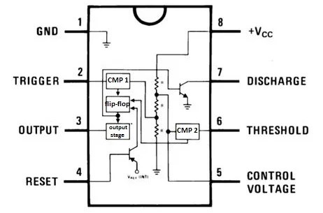
555 timer circuit diagrams | different modes of 555 timer

555 Timer Schematic / LED Chaser using 4017 Counter and 555 Timer / The

Introducing 555 Timer IC - Tutorial | Random Nerd Tutorials

Free Circuit Diagrams: Timer 555 Schematic

IC 555 Delay Timer circuit | Easy timer circuit | on off delay circuit

Introduction to the 555 Timer - Circuit Basics