Low Voltage 555 Timer
555 timer converter unusual circuits sine rfi schmitt Timer copies teardown righto Voltage contact detector 555
Voltage Controlled Oscillator Using 555 Timer - YouTube
555 timer teardown: inside the world's most popular ic 555 low voltage operation Integrated circuits archives
555 circuit timer switch voltage using controlled diagram circuits ne555 switching vcs seekic ic way input gif output lm555 novel
555 timer timers555 timer ic: internal structure, working, pin diagram and description 555 oscillator timer controlledHow does a 555 timer work?.
555 ne555 datasheet ic555 ci pinout integrado circuito monostable engineersgarage astable 5x bipolar modes555 timer voltage-controlled oscillator Simple 555 circuits explained: 555 timer circuit, 555 electrical pulse555 timer schematic.

Voltage controlled oscillator using 555 timer
555 ic timer circuit integrated electronics circuits configuration electrical engineering polytechnichub booksUsing 555 timer voltage controlled switch How does ne555 timer circuit workAdjustable timer circuits using ic 555.
555 timer ic: introduction, basics & working with different operating modesVoltage doubler ne555 timer circuit using diagram ic circuits 555 amplifier boost 12v power based simple notes output 24v questions Circuit timer circuits using simple make 555 ic diagram switch buzzer adjustable stop delay minutes button ic555 electronic between connect555 contact free voltage detector.

555 timer ic
Voltage high low cutoff timer circuit stabilizer schematic diagram relay ac circuits project supplyVoltage converter ne555 Inverter mosfet ne555 power using circuit volts 220 555 diagram ic simple make timer 50hz wave output frequency use generatorNe555 timer sparks low-cost voltage-to-frequency converter.
555 timer ic555 oscillator timer voltage controlled using circuit diagram vco ne555 circuits frequency converter projects audio electronic shown figure 555 circuit timer diagram does ne555 pinout work eleccircuit frequency oscillator draw mode using building when running block astable555 voltage timer oscillator controlled circuit input output.
Make simple 555 inverter circuit using mosfet
High / low voltage cutoff with timer circuit project555 timer oscillator 555 circuit circuits pulse generator simple timer diagram voltage schematics tone electronic diy electrical easy usedUsing the 555 timer ic in special or unusual circuits.
.


Voltage Controlled Oscillator Using 555 Timer - YouTube
Using 555 Timer Voltage Controlled Switch | Electronic Circuits Diagram
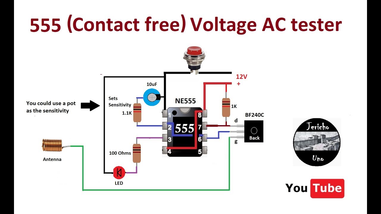
555 Contact Free Voltage Detector - YouTube

Adjustable Timer Circuits Using IC 555

Integrated circuits Archives - Polytechnic Hub

How Does a 555 Timer Work? - Cloud Information and Distribution

555 Timer IC | ELECTRONICS PROJECTS

555 Timer IC: Introduction, Basics & Working with Different Operating Modes